Monday, July 16, 2018
What Are the National CAD Standards, and What Do They Mean to Me?
Periodically, we have clients come to us asking for advice on working with the National CAD Standards (or NCS) because a client requires their drawings to be NCS compliant.
The important thing when working with clients who require compliance, is identifying what parts of the standard they want compliance with. Many organizations think of the layers standards and forget about the rest of the NCS, so may only be looking for compliance with the layer naming portion of the standards. In certain areas, there are options rather than a specific direction, so again, knowing what the client needs specifically is important. The version of the standards is important as portions of the standards have changed and included different options each version. In some cases, the standards aren’t detailed enough for design and need to be extended to support that. The standard has allowances for that. A single requirement statement requiring NCS compliance isn’t really enough due to some of those choices.
What Are the Standards?
The NCS is built from several different standards. The layering guidelines come from the American Institute of Architects. Drawing layout and construction comes from the Construction Specification Institute (their Uniform Drawing System) and plotting guidelines come from the National Institute of Building Sciences. The NCS coordinates these different guidelines into a single package. The National Institute of Building Sciences makes the standards available online through various license packages. The web address is https://www.nationalcadstandard.org/ncs6/index.php.
The NCS consists of several modules that detail various parts of the drawing process. The Modules are:
1. Drawing Set organization – Sheet order, identification, etc.
2. Sheet Organization – Sheet format, title blocks, sizes, etc.
3. Schedules – Guidelines for door, window and other schedules.
4. Drafting Conventions – Process notes for projects.
5. Terms and Abbreviations – Standard terms.
6. Symbols – Standard blocks organized by MasterFormattm divisions.
7. Notations – Guidelines for adding and linking notes.
8. Code Conventions – Regulatory annotations.
The layer standards have their own set of documents, including a Microsoft Excel file with the layering guidelines and a PDF describing how the standards work. The standards basically consist of a discipline indicator, a major and minor group (or two) and followed by a status or phase.
In addition, there are plotting guidelines, Excel sheets for samples and a set of blocks to match the standards.
The Standards and Autodesk
The industry specific versions of AutoCAD (Civil 3D, Architecture, MEP, etc) include templates with NCS layers (technically AIA layers) implemented. For example, Civil 3D includes the Autodesk Civil 3D (Imperial) NCS.dwt template which includes an implementation of the layers, complete with a number of layer descriptions filled out.
The challenge is there are no status indicators. For example, existing layers should include a status indicator to segregate new from existing or objects to be demolished. So that could potentially multiply the number of layers substantially. And of course, with Civil 3D, the BIM objects are managed as objects, such as surface, so the sub objects like contours, are dependent on the style definitions. So the surface itself may need to be on C-TOPO-D (to be demolished) or C-TOPOP-N (new work). The organization then decides whether it is necessary to create styles differentiated by status as well.
The need to explode the drawing to AutoCAD and remove the BIM objects would necessitate styles with layers detailed with that differentiation.
In the way the layers guidelines are applied to different projects or organizations, the same types of questions and answers should be generated for the other modules. For example, the sheet identification. The sheet organization describes methods and options for numbering sheets, but only addresses design sheets, and doesn’t address models or data references. Does the project require Level 2 discipline identifiers (ET for Electrical Telecommunications) or just the Level 1 (E for Electrical)?
Ultimately, the requirement to comply with NCS standards should be the start of a conversation and being familiar enough with the standards so you can address these questions can save a lot of time trying to figure them out during the design or save some heartburn during submittal. In the end, the goal is to get the design date integrated in with existing, operational data, and the standards are the key to migrating data from multiple sources.
BIM to GIS: Getting Your Pipe Network into a Shape File
One of the hot topics, particularly for me, this year at Autodesk University, was the announcement of the partnership between Autodesk and ESRI, the makers of ArcMap, the prominent GIS software around the world. The goal is to add more interoperability between BIM and GIS. To get started today, I’m going to address at least one piece of that puzzle. In the infrastructure environment, more often than not that’s going to include pipe networks. With Civil 3D we already have the model-design workflow identified. We model pip networks in Civil 3D, push them to SSA, run the models and adjust the design, and then push them back to Civil 3D. But after the design, it’s important to get those pipe networks into our GIS for long term operational management.
Some people are aware of the Export Civil Object to SDF on the Output ribbon, but I don’t run across too many people who are familiar with the format. SDF is a Spatial Data File, and is a GIS format, but it is pretty much exclusive to Autodesk. It’s comparable to an ESRI personal geodatabase. It’s designed for a single user, and can carry multiple feature classes. The fact that it’s pretty much an Autodesk format stops most folks as other GIS systems don’t support it. It needs to be transformed to a more universal format.
So we’re going to convert it to a shape file, which is pretty much the de facto universal transfer format. The first step we do is get our pipe networks ready, and then go to the Output ribbon to select the Export Civil Objects to SDF command.
Then it opens the Export to SDF Dialog. It prompts for the new filename and location, and the projection you want to use for the data. Once you select OK, the export is completed. It doesn’t prompt you for which civil objects, as it will export all of them. Since the SDF file manages multiple feature types, they all go into the same file.
At this point I find it useful to connect to the data to review the results, and we’ll need the connection to get it to a shape file.
You’ll need to open the Map Task Pane either by changing to the Planning and Analysis Workspace, or turning on the Map Task Pane on the Home Tab.
Once the Task Pane is up select the Data icon at the upper left and select Connect to Data.
Be sure to select the Add SDF Connection, and then add a Connection Name, and then locate the SDF file you just created.
The different data sets come through from the possible civil object groups. All of the data sets will show even if you have no data in them. In our case we are going to select the pipes and structures and Add them to the Map. The data in the SDF file should now overlay the objects in your drawing. I find it’s a great wat to verify all of the data came through.
Now we’ll want to go back to the Data Connections and this time use the Add SHP Connection and use the folder option and select the folder where you want to create the new shapefiles. Connect, but don’t add anything to the map.
Next we go back to the Data button on the Map Task Pane, and then select Bulk Copy.
The Bulk Copy dialog box is a bit confusing at first look, but is intuitive once you understand it.
The Source side is the original data set, and in this case, the SDF data with either the pipes or structures as layers.
The right side will be the new shape file. Select the checkbox for Structures (or Pipes) and all the lower boxes should get selected. These are the different attributes in the feature class.
In the target box, select the new shape folder connection name. Select the check box in the area below, and the names from the left box (the original SDF) will be copied over to the right side (the new shape file). I typically rename the Schema to Structures or Pipes to keep things clear – select the field and it should allow text editing. The other requirement is to change the Autogenerated_SDF_ID by selecting and retyping it to ID - The shapefile only allows field names up to 8 characters.
Select the Copy Now, and the new shape file gets created. Add it to the Task pane to compare and validate the copy. Use the same process to finish the other part of the networks (pipes or networks) and you now have a shapefile that can be incorporated to your enterprise GIS.
An Oldy But Goody - MAPCLEAN
A few days ago I was working with someone to prepare some CAD drawings for GIS Conversion, and we had to do some mass changes on the AutoCAD linework. They were unaware of some core commands they had in Civil 3D to make those tasks easier. Thinking about it, I recognize that a large percentage of users probably have no idea some of these tools exist, but they go back to the very beginnings of AutoCAD Map 3D – actually, to the ADE addon package that eventually became Map 3D. These are the Map Clean Up tools (or as they are labelled now, Drawing Clean Up). These tools are very powerful, and to my mind justify upgrading to Map 3D from AutoCAD by themselves. They are primarily designed to clean up CAD data to build geospatial data sets, but can be used to modify AutoCAD objects for any reason.
The Drawing Clean Up tools are found on the Planning and Analysis Workspace on the Tools ribbon. Look for the Map Edit panel, and the large icon is the Drawing Cleanup tools.
For those who don’t want to change workspaces, you can also get to the command by typing MAPCLEAN at the command line. When you start the command, it opens up a “Select Objects” dialog box. That box allows you to select drawing objects you want to modify. You can select all or pick and even select specific layers to pull from. On the layer selection, you can use wild cards, and select for example, c-road* to select any layer name that begins with c-road (c-roads-cntr, c-road-edge, etc).
The bottom half allows you to select items that can be used as reference points that aren’t altered or moved, such as monument points you want to maintain during the cleanup process.
After finishing the object selection and hitting next, you get to the Cleanup Actions dialog. This is the meat and potatoes of the tool set.
You can select one or more of the cleanup actions you want to use.
Delete Duplicates – Exactly what it says – it removes duplicate objects. It will also remove objects that are close to duplicate depending on the parameters – essentially you can specify a tolerance.
Erase Short Objects – Deletes any linear objects shorter than the tolerance.
Break Crossing Objects – breaks lines whenever they cross (see below):
Notice the crossing lines circled on the left, and after the command, grips showing the ends of the lines on the right image.
Extend Undershoots – When a line is just short (based on the tolerance parameter) of reaching the end another object, the tool will extend the line to that point.
Apparent Intersection – When lines look like they should intersect but are too short, this will extend them to the intersection. The parameter is the radius distance between the two.
Snap Clustered Nodes – When there are multiple end points close to each other but not quite touching 9based on the tolerance parameter), the tool will move them to snap together. This is an example where anchors can help – the ends of a road centerline, for example, can be snapped to an anchoring monument.
Dissolve Pseudo Nodes – Removes nodes (points – or points in a polyline) within a line – such as polyline vertices that are in a straight line.
Erase Dangling Objects – Deletes lines that have an endpoint not shared by another line. Tyically used to remove lines that are not part of polygons in a data set.
Simplify Objects – Removes nodes that are within the tolerance on 2D lines. It is also called generalizing.
Zero Length Objects – Removes objects that have no length, such as a line with the same start and end point. This is often why Zooming to extents can cause your drawing to open a huge area where there’s no apparent linework.
Weed Polylines – Simplify objects for 3D polylines.
One of the best parts of this tool set is the ability to make these changes en masse in the drawing. Thousands of updates can take place at once. At the bottom of this dialog, you can apply the edits automatically, or by manually reviewing and approving each change.
You can mix and match the edits to save time, but keep in mind some of these actions actually oppose each other, so combining them can defeat the purpose or do nothing at all. I remember when it first came out thinking it would help to do all the actions at once. Instead it just made a mess of the drawing.
The next dialog – “Cleanup Methods” gives you the option to determine whether you want to change the original linework or create new cleaned up objects (and the layer to store them), and how the objects will be modified.
The last dialog box of the command will only show if you choose interactive edits. Then it shows how to label the various types of edits with colors and symbols. This is very handy when you a looking at the street network of a large town, for example.
These tools have been a real lifesaver for me at times, and I hope you find them useful. One of the best ways to get familiar with it is to create a drawing with various lines, symbols, crossings, etc and trying the tools one at a time. Then when something comes up in production, you know the tool is there and how to use it.
I also put this in a video on the Autodesk Knowledge Network.
Getting a Better RFP for Geospatial Projects
So I posted a screencast to the Autodesk Knowledge Netowrk on getting a better RFP for geospatial projects. I actually posted it just over a year ago, but I thought it would be good to refresh it as so many RFP/RFQ/RFIs we get are still written in a way that it's difficult to actually get a good contract with a high potential for success. The goal is getting multiple, high quality bids and get the services you need.
If you are looking to get a geospatial project, here's some ideas to get better responses.
If you are looking to get a geospatial project, here's some ideas to get better responses.
Insert Satellite Imagery in Map 3D and Civil 3D
Imagery of all sorts has become so important to design and geospatial projects that it’s almost ubiquitous. And most people are familiar with the Bing Map tools built into Civil 3D and Map 3D now. But we often have requirements for imagery that’s more dynamic or serves a different purpose, such as multi-band satellite imagery. So let’s look at how we can bring in this imagery into Civil 3D to use for our design or analysis.
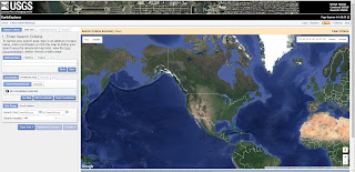
First we need to find our imagery. I’m going to hit the USGS Earth Explorer to download some High Resolution Orthoimagery. I won’t show how at this point – there’s a number of tutorials on the site. But you select the area and type of data you want, and it will generate a download package and link.

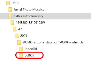
 The download package provides a ZIP archive with several stacked directories – depending on the specific data set. Navigate the directories to find the actual image files.
Specifically here, we’re looking for the TIF, which is the image, and the TFW, which is the world or correlation file. The world file tells AutoCAD where the image is in the world. We need both to effectively place the image in its correct geographic location.

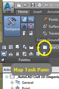
Now we’ll go into Civil 3D or Map 3D and load the image. We’ll need to have the Map Task Pane open. If it’s not we can open it by going to the Civil 3D Palettes ribbon and expanding it.
Once it’s open, go to the Data icon at the top right. Select Connect to data.
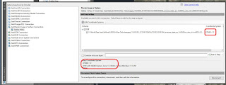
 Select the Add Raster Image and we’ll go find the image we just saved in the Source File or folder box – note you can use the folder to load several images at once. Be sure to select the image itself – the TIF. AutoCAD will recognize the world file automatically. We can add a name for the connection, and then hit connect. It will bring up a status box, and once it finishes creating a connection you can select the image and add it to you Map.
Note that it will read the project, and if your drawing has no coordinate system it will assign the one from the image. If there is one, it will generally re-project to fit the coordinate system where possible. At this point, you also have the option to combine multiple images (if you have them) into the screen.
Depending on the size, it may take a little while, but the image should come into your screen at the correct coordinate system and scale.
This method keeps your performance pretty good as it samples based on your current view scale. You can see the link to your image connection in the Map Task Pane and use the check mark to make it visible or invisible.
Good luck with your imagery!
Subscribe to:
Comments (Atom)


