Wednesday, May 5, 2010

Try Out a Map Book


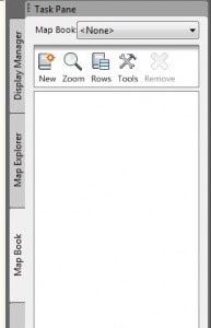
On the Task Pane of AutoCAD Map 3D, there is a series of tabs. I spend a lot of time demonstrating and talking about the first two, but I don’t spend much time on the third one – Map Book. The Map Book tab is simply a set of tools designed to help users generate an easily reproducible set of printed maps. It will generate a standard AutoCAD Sheet Set, but will include some tools specifically designed to simplify setting up a grid-based Sheet Set, complete with a key map and navigation features.
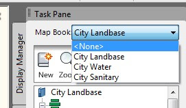


You can also have a number of Map Books defined. You may want different books for different utilities, or you may have different scales needed for different map sets. Moving back and forth is just a matter of selecting the appropriate map book at the top of the task pane.

Before creating a new map set, you need to make some decisions. You will need a template drawing file with a layout defined with a title block, and if desired, the adjacent navigation blocks, main, key view and legend viewports. There are a number of templates to use as examples that come with Map. You can find them with the other templates in \Documents and Settings\\Local Settings\Application Data\Autodesk\ AutoCAD Map 3D 2010\R17.2\enu\Templates. These templates may net perfectly suit your specific application, but they can give you some ideas.
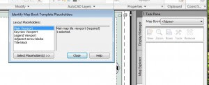
You can open one of these and use the Identify Template Placeholders command from the Tools button to look through the settings.


Once you have everything ready, you can use the New button to start a new map book. As with most things Map, you will get a workflow-based dialog box. Go through each section of the dialog before closing the dialog or hitting the generate button.

First, you’ll set a name in the Source. You will select Map Display if you’re plotting objects from the Display Manager (primarily FDO connections) and Model Space if you’re selecting AutoCAD Objects. Remember, you can add Objects from model space into the map display.

Your next step is to select the template drawing file, with the Layout and Title Block you’ve setup. At this point you can add the links to adjacent sheets. You will also set the scale here.
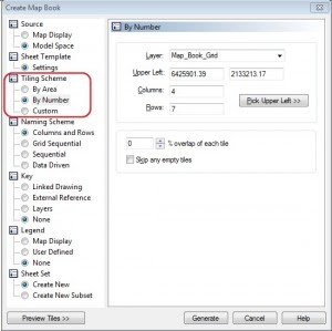
Next, you will set up your map grid using a Tiling Scheme. You can set the grid based on the size of the map (area), by the number of sheets you want, or by selecting a premade grid made from existing closed polylines. You can also set a map overlap, so that you can have a strip of surrounding area. You do that with a percentage.


If you want to create an overlap, and still keep scale maps (I’m not sure who wouldn’t), a friend of mine, Jeremiah McKnelly wrote a great tip for getting true scale map books with an overlap. Check it out here.
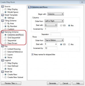
The next step is to set a naming scheme for your grid. You have several options based on numbers, letters, or you can even use data from the drawing using the expression builder.

Next you can define your key drawing. You can use premade keys, or generate one on the fly by selecting the layers you want to show.

You can then add a legend where map will setup the viewport if you’ve already created a legend, or you can set up a space to add one later.

Finally, you get to define where you’ll put your sheet set definition file (.DST).
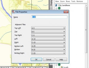
After all this, your Map Book tab will now display all the sheets with their views. You can check the properties of one of the views to see the adhacent sheet information stored. You will also see all of your new layouts, all named and ready to go.


The process allows you to very quickly layout some simple sheet sets with very minimal effort. If your organization needs to plot map books or sets of printed maps, this may be the right tool for

Friday, March 19, 2010

Updating and Synching

Well, I finally took the opportunity to synch up my professional GIS blog with my personal GIS blog. There are some goofy spacing issues, and the image html doesn't work exactly the same between the systems - I haven't seen what's causing it yet. But at this point, I'm caught up.

Losing Your Religion: Interoperability with AutoCAD Map 3D and ESRI, Part 2

A little while ago I started this interoperability discussion by discussing the similarities between CAD and GIS, primarily Autodesk’s AutoCAD and ESRI’s ArcGIS. Now I’ll talk about the critical differences between them, or at least the data formats. These differences are critical to understanding how to manage interoperability.
There are two primary areas of difference. One is the data structure paradigm, and the other is the graphic representation. AutoCAD drawings and ESRI data sets store data in fundamentally different methods. They are both forms of databases that store information about the location, properties and appearances of the various objects, but because they have substantially different requirements, they have to organize the data differently.

Data Structure Paradigm
CAD is used for all types of drawing. The CAD drawing file is essentially an object-oriented database which stores objects sequentially (essentially as they’re drawn). Each row of data will represent an individual CAD primitive object. The structure of the data and the number of elements is dependent upon the type of primitive. For example, a point is going to carry a single coordinate pair (X,Y) for its location while a line will store two coordinate pairs – a start point and an end point. A curve will have a start point, an end point, and a bulge (or curve) factor. Along with that, there are additional data elements describing the color, line type, layer and other properties.


Entity IDLineSt PointEnd PointLayer
Entity IDPointIns PointLayerColor
Entity IDBlockIns PointLayerColor
Entity IDArcSt PointEnd PointBulge

An ESRI GIS dataset, whether it is a shape file, geodatabase or personal geodatabase organizes the data into more formal structures, in the form of tables (this is simplified to a conceptual level – each of these data formats include several files or tables to complete the dataset, but are not really germane to the discussion). Different primitives, such as points, lines and polygons can’t reside in the same set of tables. In addition, the number of data elements in each row will be consistent with the dataset. Points representing valves will be in a different table than the lines representing the pipes they’re attached to. The tables will be divided based on some set of business rules to organize the data. In the ESRI terminology, this is essentially a Feature Class. For example, water, storm and sanitary sewer lines may all be in one table, or they may be divided into 3 or more tables. The division may be due to organization, or due to the different information needed for each group. Many times within each Feature Class, there will be a further subdivision of objects, such as high-voltage conductor and low-voltage conductor, called a Subclass. Typically the subclass will be the level of organization used to symbolize the objects. The result is a very structured organization of data.


Feature Class (Pipes – Lines)
IDShape (BLOB)SIZEMATERIALIN USE


Feature Class (Vegetation – Polygon)
IDShape (BLOB)SPECIESAGEAVG DBH

The analogy that I typically use, and it seems to fit, is that the data sets are like a collection of coins. My AutoCAD file is like a pile of change and my ESRI data file is like the same group of coins all organized into paper tubes.
coins


The take away from all of this is that an AutoCAD drawing will store multiple data types in a single drawing file, while the ESRI data sets will store multiple data types in multiple tables (and/or files). This is a critical point to managing interoperability.


Graphic Representation
The other major area of difference is with the graphic representation. The AutoCAD drawing includes information regarding the appearance of the objects. For example, a line will include the color, line type, and thickness. Each of these properties is inherent in the primitive object. These properties define how AutoCAD will display the file. If I pass the file to someone else, and they open it, it will look the same.
ESRI datasets are a different case. The datasets are not related to the appearance of the data. The appearance is left up to the application at the time of display. ArcGIS, for example, stores the appearance of a map in a Map document, which contains pointers to the data, describing what data to select (allowing a subset of the data through a query) and how to display it. It is the map document that contains the symbolization information, such as linetype, color and stylization.

viewing
The Result
These two differences present the primary difference to interoperability. Neither one nor the other is inherently better - they have different ways of achieving similar results. The data organization presents some challenges when bringing CAD data into GIS tools, for example, when reading an AutoCAD DWG file in ArcGIS, it reads the data as if it were ESRI datasets, and groups objects by their primitive forms, such as lines. That’s different than the way CAD users think of and manage the data. Additionally, CAD drawings typically contain information that doesn’t fit into the GIS data model. The separation of the data from the symbolization is what allows GIS systems to display the same information is many ways depending on the view or analysis needed. This also makes it a little more difficult when transferring data between systems. There is no direct method within AutoCAD to read the Map document to get the shortcuts and symbolization and replicate an ArcGIS map without recreating the symbolization. In most cases this is not really an issue because the data is the important part, although it can be problematic when you want to reproduce the entire map.
There are some other differences between systems that are important to be aware of, such as shape files not dealing with arcs (causing arcs to be broken into many small lines), and single or double precision data differences. These are important to be aware of, but not as critical to the basic interoperability of the systems.

One of the reasons I like working with Autodesk's AutoCAD Map 3D product is that it provides me with both worlds. It is an AutoCAD drawing, and with the Feature Data Objects connectors, I can work with the ESRI datasets natively without having to make any changes in the way I work with these disparate data types.

In most cases, there are business issues that interfere with interoperability that have a much greater impact than these technical software elements. I’ll explore those in a future blog.

Where'd My Property Go: Finding data during Splits and Merges

One of the challenges when working with geospatial systems is managing the data attributes when the object is split or combined with another. For example, if I have two parcels that are joining, and they have different Assessor Parcel Numbers (APNs), how do I get just one new APN from the 2 previous APNs. And what happens to the area field? Or when I split a parcel, how does the system name the 2 new parcels? More importantly, that about the ID field that serves as a key to link to other databases. The answer is that you can pretty much set it to do what you want. AutoCAD Map incorporated split and merge tools so that you can manage them. The following example should give you an idea of how to get started. The important thing is that like most things GIS, putting some thought into it prior to trying to do the work will give you the best results. In other words, design is very important.

My example will use a proposed forests data set. I have attributes for the proposed name, the area, perimeter, and the area in square kilometers and hectares. During the join, I want to rename to proposed forest, and update the area and perimeter fields.

NOTE: As I go through this, keep in mind the terminology gets wonky. The same words can be used to describe multiple elements of these objects. For example, the attributes of a feature can be called attributes, properties, fields and columns (to us database geeks), and the properties describing the said attributes, such as field size and type, can all use the same names. So, try not to read too much in the wording and I’ll try to match AutoCAD Map’s terminology.

To set the Split and Merge Rules, I will highlight the target data set in the Display Manager and open the Data Table.
OpenDataTable


Once I get the Data Table open, I’ll select the Options, and select Set Split and Merge Rules.


SelectDataTableOptions

At that point, I’ll get the Split and Merge Rules dialog box.
SMRulesDialog
At the left of the box, I get a list of all of the feature properties of the selected data set (attributes or database columns). As I select each of these properties, I get the various attributes of that property. It identifies whether the property is an Identifier, the data type of the property, whether it is autogenerated, read-only or nullable. In addition, I can set Split and Merge Rules for each property attribute. Keep in mind, the available Split and Merge Rules are context sensitive based on the data type (it’s a little tough to sum text fields).

The data set I’m using is an ESRI shape file, so there are certain feature properties that are inherent because of the type of data set. The FeatID is autogenerated and read only, so I won’t be able to set any rules for this one.

My ID field is an identifier for the individual forest polygons. I’ll set my Merge Rule to Empty. When merging, I’m going to create a new and distinct record from the previous record. This is a business rule I’ve decided upon so I can keep a history of forest proposals, even if they are not actually implemented.

My area field shows the area of the polygon. I could add the polygons, but for better results I can use an expression to calculate the actual area of the result. To do this, I set my Split rule to Calculation, and select the Expression Builder button (next to the Exporession box). I’ll select the Area2D from the Geometric pull down,

expressionarea
And then Geometry from the Property pulldown.
expressionGeometry

The resulting expression, Area2D(Geometry) , will calculate the area of the new polygon (if you know the expression, you could just type it in the box rather than going through the expression builder – but if I had done that, you wouldn’t have seen it, right?). That expression will go into both the split and merge rules.
My next feature property is the Perimeter, and guess what? There’s a calculation for that as well. Select Length2D in the Geometric pull down to get this expression: Length2D(Geometry)
On the Name feature property, I will generally not use the existing names – again a business decision. There are cases where I would want to keep one of the names (Using the FirstSelected or LastSelected rule) or concatenate the two names, just not for this case. In my example, I would need to add the name manually after doing the merge (or split).
My next feature property is AREASQKM, or the area in square kilomters. I can use the same expression as before, but include the conversion to square kilometers, giving me this expression: Area2D(Geometry)*0.00000009290304. Again this will apply to both split and merge.
My last standard property is HECTARES, which is the area in hectares. This will match the previous bit with the appropriate factor: Area2D(Geometry)*0.000009290304

Of course the last entry is Geometry, and you can’t use rules on geometry,

Adding Custom Linetypes

My last post was on the linetypes for feature objects in map 3D. There are a lot of options, but it isn't as open as using AutoCAD linetypes. You can create additional stylization, but it takes rolling up your sleeves. My next post was going to do that, but I don't have to - Murph did. So check out his post on adding custom linetypes, and I'll work on something else.

Finding Your "Type"

One of the common questions I after folks start working with Feature Data Object connections in AutoCAD Map 3D is how to use interesting linetypes in their maps. To add linetypes to FDO-connected data sources, select the ellipses next to the Thematic Rule in question, and the Style Line dialog box opens. There you can select the thickness, color and pattern for the line.
StyleLineBox

The pattern selection provides a set of linetypes – not the AutoCAD Linetypes (there is no direct way for users to modify this list, although it can be programmatically edited – more on this another time). This will provide a number of options and style combinations.
You can also stack line patterns to create more complex styles. For example, many road maps will use a red line with black borders for a highway, sometimes with a back center line or dashed line to show divided highways. This can be modeled by using several lines patterns overlying each other. StyleLineBoxexp
To do this, select the composite lines option. The Style Line dialog box will then expand to add a composite style box where you can add multiple line components.


HwyLineStyle
To make the example highway style, add 2 new lines by clicking the New button at the top of the composite box. Select the line at the bottom, change it to a .2 cm thickness at black with a continuous pattern. Change the middle line in the box to a continuous red line with a width of .15 cm. Change the top line to a black line with a dashed pattern at a .1 cm thickness. The resulting line style will be apply to this theme rule throughout the drawing.

You can have different composite lines for each theme rule, allowing fairly complex maps. Combine these with some annotation patterns and you can make maps that look like the standard road maps from various publishers.

Happy GIS Day! Here's some Arizona GIS Data Sites

Today is National GIS Day! (at least it was when I originally posted it)

CADsoft Consulting's CAD Camp 2009 is well underway. We had a very successful Architectural/BIM day yesterday, and the Civil day is in full swing. Tomorrow will be the Geospatial Day (so it doesn't interfere with any GIS Day activities). This morning we've had a presentation from Autodesk's Civil 3D maven, Lucy Kuhns, and our own Ron Coulliard is doing a workshop on grading as I type. During Lucy's presentation, I was asked about local Arizona GIS data, so I promides to share some of the sites I use/am aware of. The list is by no means exhaustive, and there's some dupplication within the sites, but here you go anyway. I'll continue to identify sites I run across in the future. If you've got some good ones you want to share, add them to the comments or email to me and I'll add them to the list.

GIS Data Sites for Arizona

Arizona State Cartographer's Office
They maintain the Arizona GeoServer, with aerial photos and statewide features served through web mapping services (WMS) and web feature services (WFS). They also maintin links to other data sources throughout the state

The AGIC (Arizona Geographic Information Council) GeoData Portal
AGIC is a state sponsored group working with GIS across the state. They sponsor an annual GIS educational conference every year. We just finished the 2009 conference in Tucson. There was great attendance. I presented 3 hands on worksops this year. They have County boundaries, tribal boundaries, cities, wilderness areas, political boundaries, voting districts, school districts, census information, environmental and natural resource data, interstates and roads

US Fish and Wildlife
USFW maintains larger scale data sets covering National Wetlands Inventory and area boundaries

U of A Library
The U of A Libraries maintains the Arizona Electronic Atlas and the Arizona Regional Image Archive (ARIA) as well as links to other data sites

ASU
The ASU Libraries also has spatial data and links available

ADEQ
Arizona Department of Environmental Quality (ADEQ) has water quality data, surface, drinking and groundwater

Local division sites

Maricopa County
The County Assessor's Office GIS Department maintains data for the county including parcels, detailed topographic data, floodplains, and survey network.

Pima County
Pima County is really one of the long runners in GIS. They have had data available for as long as anyone in the state. They maintain over 273 data layers in ESRI shape files as well as landbase section maps in AutoCAD format.

City of Phoenix
Phoenix has an extensive collection of GIS data. They have Engineering Quarter-Section maps in DXF format CAD files

Nationally-based sites

US Forest Service

FEMA
The Federal Emergency Management Agency maintains flood hazard data sets which are available as GIS data sets or through a Web Mapping Service (WMS)

NSGIC
The National States Geographic Information Council maintains an inventory of data and its currency in the Ramona GIS Inventory. Arizona's page is here:

Natural Resources Conservation Service (NRCS)
The NRCS maintains the Soil Data Mart with soil data available by state. They also collect other data such as water supply and snowpack

United States Geological Servey (USGS)
The USGS maintains large scale data sets for the US. They have digitial orthoquads and photos, land cover, elevation model and other data sets.

US Census Bureau
The Census maintains census and popluation data for the US

United States Department of Agriculture

USDA has Forest Coverage

Geography Network
The Geography Network maintains various spatial data sets for the US

ESRI Geoportal Extension
ESRI has a beta site with downloadable GIS data

National Center for Atmospheric Research
Atmospheric data for the US


New Mexico

Lucy Kuhns mentioned the New Mexico Resource GIS program site. Here's the link:
http://rgis.unm.edu/

Losing Your Religion: Interoperability with AutoCAD Map 3D and ESRI - Part 1

I’ve been speaking at conferences for several years about CAD and GIS interoperability. It’s one of those topics where there’s a lot of interest and a lot of misinformation. Or at least, it seems to be much more difficult than it really is. I’ve been moving data between both systems for years, with very few real challenges. What I’ve found, is that the real issue is not the technical aspect of moving data back and forth, but the differences in how the software is generally used. AutoCAD (and other CAD systems) are primarily used for doing design work, and GIS (ostensibly ESRI, but it could be any GIS system) is primarily used for managing as-built facilities and systems. The real challenges are working between the design and as-built management processes. In other words, the issue isn’t CAD to GIS, the issue is Design to As-Built.

I’m going to make several blogs here in a series of the issues and some methods to make the process easier. This first post, I’m going to discuss the a bit about the similarities in the technologies. Following that, I’ll be posting on the differences, barriers, myths, and other issues involved.

Both AutoCAD and ESRI are built on basic primitive elements that are combined to create representations of real objects. Both systems include:

Points - a representation of a single location. It could represent a physical object such as a pole, manhole or brass cap in the ground, or it could be a non-physical point, such as a crime scene location or the corner of a property line. In any case, the systems both record a coordinate consisting of an X and a Y and possible a Z (if elevations are being included). The X and Y value could represent any projection or coordinate system, such as degrees of latitude and longitude or northings and eastings from a state plane.


Lines – a representation of of a connected set of coordinate pairs. Every line is going to have a start point defined by X, Y and/or Z, and and end point defined by an X, Y and/or Z. It could represent the centerline of a road, the edge of a building, or a buried pipe.


The line may be defined the system by coordinate pairs, such as point A and point B, or it could have the actual coordinate values in the line definition, such as this example from AutoCAD (a listing of a line – the start point is the set of parenthesis with the 10 X Y Z, and the end point is 11 X Y Z):


In some cases, for example, ESRI, the actual coordinates of the line are stored within an object “envelope”, which is a rectagle enclosing the object.


Polygons – a representation of an area. It could be a representation of a parcel, a building footprint, or an animal migratory zone. It is defined by lines and so by a series of bounding coordinates. Generally, in vector systems (save that discussion for another time), polygons are defined by their boundaries. They could be defined by groups of lines, or it could have the coordinate values built into the definition, simlar to the lines (as shown above).


In ESRI, the coordinate pairs are contained in an envelope bounding the entire object:


Attributes - data associated with an object. Associated data could be an identification number, a name, a description of the object, the color, size, diameter, etc. This is what turns a simple point, line or polygon into a representation of a fire hydrant, electric line or county. Attributes may be stored and linked to the object in a myriad of methods. It could be based on a common identifier stored in the object definition and the attribute list, as in a primary-foreign key relationship, or the definition of the object may be created to include certain atribute sets intrinsically. In some cases there may be a mixture of methods. For example, in AutoCAD, objects have intrinsic attributes (such as blocks attributes), extended entity data (attribute values associted to an individual object), or object data (data tables stored internally in the drawing and linked to objects). Additionally, both systems include methods to link objects to externally associated databases to extens the attributes of an object.


Understanding these similarities is key to understanding how to integrate these two systems. The next post, I’ll discuss the primary differences between the two.